By Muhammad Ibrahim · Published October 27, 2026 · 10 min read
K-Map Simplification Example: Simplify Two 3-Variable Functions and Build the Circuit
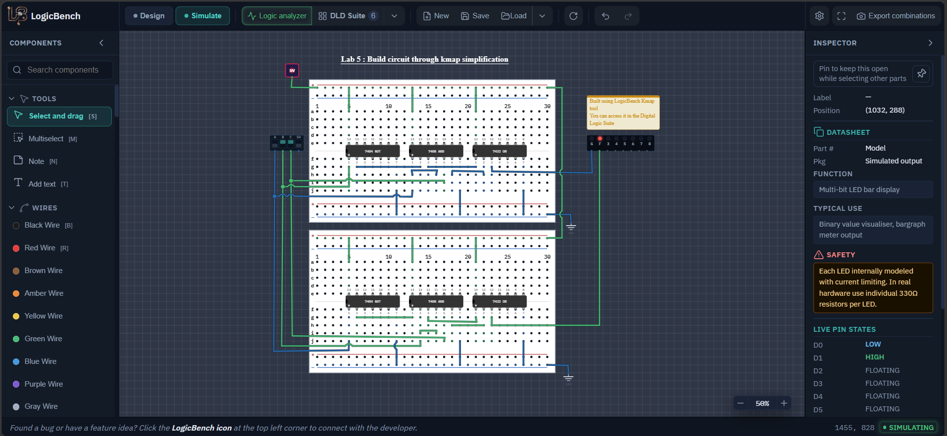
Lab 5 is about turning a truth table into the smallest circuit you can build, using a Karnaugh map. My circuit file has two functions on two breadboards, F and G, and both are driven by the same three switches A, B and C. Below I simplify each one on its map, show which groups I picked and why, count how much smaller the circuit gets, and then wire it up. The circuit was generated with the K-Map solver in the Digital Logic Suite, and you can use that tool to check your own answer when you are done.
- CHIPS
- 2 sets of 7404, 7408, 7432
- GATES USED
- 8 (4 for each function)
- INPUTS
- 3 switches (A, B, C)
- OUTPUTS
- 2 LEDs (F, G)
Components needed for the K-map circuits
- Two 7404 (hex inverter), two 7408 (quad AND) and two 7432 (quad OR), one set for each function
- A DIP switch with three switches in use, renamed A, B and C
- A Light Bar with two LEDs in use, renamed G and F
- A Regulated +5V Power part, two Ground (GND) parts and two half-size breadboards
Open the circuit
Open the exact circuit from the lab with both functions. Switch to Simulate and flip A, B and C to see F and G.
3-variable K-map examples: F and G
F = A'B + BC
G = AB' + AC
Rows are A and columns are BC in Gray code order. Every coloured box is one group of ones, and the small m numbers are the minterm numbers. The cell shared by two boxes is used by both groups.
Simplified F and G circuit diagram
Each simplified function needs one inverter, two AND gates and one OR gate. In the circuit file the same three switches drive both halves. Small numbers are chip pin numbers.
How to simplify F and G with K-maps and build the circuits
Write down when F and G must be 1
F is 1 for ABC = 010, 011 and 111. In minterm form that is F = Σm(2, 3, 7). G is 1 for ABC = 100, 101 and 111, so G = Σm(4, 5, 7). Every other input combination gives 0 for both. The full table is below.
Draw the K-map for F and pick the groups
Put A on the rows and BC on the columns, and write the columns in the order 00, 01, 11, 10. That order is a Gray code, so neighbouring cells differ in only one variable, and that is what makes grouping work. F has ones at 010, 011 and 111. Group the two cells in the row A=0 under BC=11 and BC=10. Both have A=0 and B=1, and C changes, so that group is A'B. Then group the cells 011 and 111. Both have B=1 and C=1, and A changes, so that group is BC. The cell 011 is used in both groups, which is allowed. F = A'B + BC.
Draw the K-map for G and pick the groups
G has ones at 100, 101 and 111. The cells 100 and 101 have A=1 and B=0 while C changes, so that group is AB'. The cells 101 and 111 have A=1 and C=1 while B changes, so that group is AC. The cell 101 is in both groups. G = AB' + AC.
Build G on the first breadboard
On the 7404 connect B to pin 1, and B' comes out on pin 2. On the 7408 the first AND gate gets A on pin 1 and B' on pin 2, so pin 3 gives AB'. The second AND gate gets A on pin 4 and C on pin 5, so pin 6 gives AC. On the 7432 connect pin 1 to the 7408 pin 3 and pin 2 to the 7408 pin 6. Pin 3 of the 7432 goes to the LED named G.
Build F on the second breadboard
On the second 7404 connect A to pin 1, and A' comes out on pin 2. On the second 7408 the first AND gate gets A' on pin 1 and B on pin 2, so pin 3 gives A'B. The second AND gate gets B on pin 4 and C on pin 5, so pin 6 gives BC. On the second 7432 connect pin 1 to the 7408 pin 3 and pin 2 to the 7408 pin 6. Pin 3 of the 7432 goes to the LED named F.
Power both breadboards and share the switches
Every chip needs pin 14 on +5 V and pin 7 on ground. In my file one +5 V part feeds both boards and each board has its own ground part. The three switches are wired to both boards, so A, B and C control F and G at the same time.
Check against the truth table, not against your equation
Run all eight combinations in Simulate and compare the LEDs with the truth table you started from. Do not compare with your simplified equation. If you made a mistake in the K-map, the circuit will faithfully build that mistake and agree with your equation, and only the original truth table shows that something is wrong.
Truth table for F and G
| A | B | C | G | F |
|---|---|---|---|---|
| 0 | 0 | 0 | 0 | 0 |
| 0 | 0 | 1 | 0 | 0 |
| 0 | 1 | 0 | 0 | 1 |
| 0 | 1 | 1 | 0 | 1 |
| 1 | 0 | 0 | 1 | 0 |
| 1 | 0 | 1 | 1 | 0 |
| 1 | 1 | 0 | 0 | 0 |
| 1 | 1 | 1 | 1 | 1 |
Pin connections for the F and G circuits
| Signal | Function G (first breadboard) | Function F (second breadboard) |
|---|---|---|
| Inverter | 7404 pin 1 = B, pin 2 = B' | 7404 pin 1 = A, pin 2 = A' |
| First AND gate | 7408 pin 1 = A, pin 2 = B', pin 3 = AB' | 7408 pin 1 = A', pin 2 = B, pin 3 = A'B |
| Second AND gate | 7408 pin 4 = A, pin 5 = C, pin 6 = AC | 7408 pin 4 = B, pin 5 = C, pin 6 = BC |
| OR gate | 7432 pin 1 and pin 2 take the two products, pin 3 goes to LED G | 7432 pin 1 and pin 2 take the two products, pin 3 goes to LED F |
How K-map simplification works
Why the columns are in Gray code order
On the map, two cells that touch differ in exactly one variable. That is why the columns go 00, 01, 11, 10 and not 00, 01, 10, 11. When you group two touching ones, the variable that changes between them drops out of the product term. A group of two removes one variable and a group of four removes two. This also explains why groups must have 1, 2, 4 or 8 cells: only those sizes remove whole variables.
Why overlapping groups are fine
In F the cell 011 sits in both groups, and in G the cell 101 does. A cell can be covered by more than one product term, because in an OR gate 1 + 1 is still 1. You should actually prefer overlap, because it lets each group grow as big as possible, and bigger groups give shorter product terms.
What the simplification saves
Written straight from the truth table, F is A'BC' + A'BC + ABC, which is 3 terms with 3 literals each, 9 literals in total. The simplified form A'B + BC has 4 literals. Built with 2-input gates, the unsimplified F needs 2 inverters, three 3-input ANDs (6 two-input gates) and a 3-input OR (2 more), which is about 10 gates. The simplified circuit needs 1 inverter, 2 ANDs and 1 OR, which is 4 gates. G shrinks the same way. A smaller circuit is also faster, since the signal now passes through only three gates (NOT, AND, OR) on its way to the LED.
A K-map gives the best two-level circuit, not always the smallest one
The sum-of-products answer is the best circuit made of an AND level followed by an OR level. But F = A'B + BC can be factored as B(A' + C), which needs only 3 gates: one inverter, one OR and one AND. In the same way G = AB' + AC = A(B' + C). So if gate count matters more than depth, factoring can beat the K-map result. For this lab the expected answer is the sum of products, but it is a useful thing to know.
Expected output of the simplified circuits
- LED G is on for ABC = 100, 101 and 111 and off for the other five rows.
- LED F is on for ABC = 010, 011 and 111 and off for the other five rows.
- Both LEDs are on together only at 111, and both are off at 000, 001 and 110.
- Every row matches the truth table you started from, not just the simplified equations.
K-map circuit not working? Common mistakes
The groups look right but the circuit is wrong
Check the column order of your map. Writing the columns as 00, 01, 10, 11 breaks the neighbour rule and gives wrong groups.
You circled three cells together
Groups can only have 1, 2, 4 or 8 cells. Three ones in a row are two overlapping groups of two.
F and G are swapped in the report
In my file the first breadboard drives the LED named G and the second breadboard drives the LED named F. Rename the LEDs in the simulator so you never have to remember it.
The inverter is on the wrong signal
G needs B' and F needs A'. Mixing them up is the most likely slip because both circuits look almost identical.
The second breadboard does nothing
It has its own rails. Connect +5 V and ground to them as well as to the first board.
Frequently asked questions
How do you simplify a 3-variable Boolean function with a K-map?
Draw a 2 × 4 map with A on the rows and BC on the columns in Gray code order (00, 01, 11, 10). Mark the ones, circle the largest groups of 1, 2, 4 or 8 adjacent cells, and write one product term for each group using the variables that do not change inside it. Then OR the product terms together.
What does F = Σm(2,3,7) mean?
It means F is 1 for the minterms numbered 2, 3 and 7 and 0 for all other input combinations. With A as the most significant bit, those are ABC = 010, 011 and 111.
Can K-map groups overlap?
Yes. A cell can belong to more than one group, and you should overlap groups whenever that lets a group grow bigger, because bigger groups give shorter product terms.
Why must K-map groups have 1, 2, 4 or 8 cells?
Each time a group doubles in size, one more variable stops changing inside it and drops out of the product term. Only sizes that are powers of two remove whole variables, so a group of three is really two overlapping groups of two.
Does a K-map always give the cheapest circuit?
It gives the cheapest two-level AND-OR circuit. A factored form can sometimes use fewer gates: A'B + BC = B(A' + C) needs three gates (NOT, OR, AND) instead of four.
Try it yourself
Open LogicBench and follow along — the simulator is free and needs no account.
Launch the simulator