By Muhammad Ibrahim · Published October 27, 2026 · 8 min read
Half Adder Using AND, OR and NOT Gates: Circuit, Truth Table and Wiring
Most books draw the half adder with one XOR gate and one AND gate. My Lab 2 circuit has no XOR chip at all. The sum is made from two inverters, two AND gates and an OR gate, and the carry from one AND gate. It uses more gates than it needs to, but that is the reason to build it: you see what an XOR really is, and you have a working half adder even if all you have is a 7404, a 7408 and a 7432.
- CHIPS
- 7404, 7408, 7432
- GATES USED
- 6 (2 NOT, 3 AND, 1 OR)
- INPUTS
- 2 switches (A, B)
- OUTPUTS
- 2 LEDs (SUM, CAR)
Components needed for the half adder
- A 7404 (hex inverter), a 7408 (quad AND) and a 7432 (quad OR)
- A DIP switch. Two switches are used and I renamed them A and B
- A Light Bar. Two LEDs are used and I renamed them SUM and CAR
- A Regulated +5V Power part, a Ground (GND) part and one half-size breadboard
Open the circuit
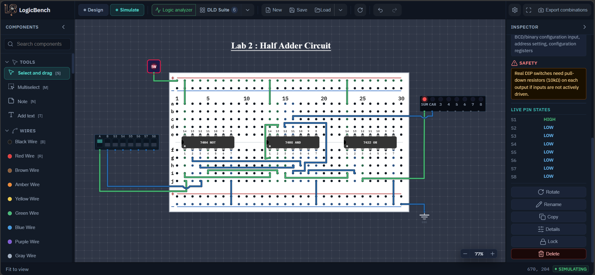
Open the exact half adder from the lab. Switch to Simulate and flip A and B. The SUM and CAR LEDs show the result.
Half adder circuit diagram using AND, OR and NOT gates
The XOR for the sum is built from the two inverters, two AND gates and the OR gate in the upper part. The AND gate at the bottom is the carry. Small numbers are chip pin numbers.
How to build a half adder with AND, OR and NOT gates
Start from the truth table
A half adder adds two single bits, A and B. SUM is 1 when exactly one of the inputs is 1. CARRY is 1 only when both inputs are 1. That gives the table below, and you can read it as binary: 1 + 1 = 10, so CARRY is 1 and SUM is 0.
Turn the SUM column into gates
Look at the two rows where SUM is 1. The row A=0, B=1 is the product A'B. The row A=1, B=0 is the product AB'. SUM is one or the other, so SUM = A'B + AB'. That is an XOR written with AND, OR and NOT. CARRY is simply AB.
The circuit needs: two inverters (for A' and B'), two AND gates for the two products, one OR gate to join them, and one more AND gate for the carry.
Place the chips and power them
Put the 7404, 7408 and 7432 on the breadboard. Connect pin 14 of every chip to +5 V and pin 7 of every chip to ground. Do this before any logic wiring. The 7432 is the easy one to forget because it is only used once, at the end.
Make A' and B' with the 7404
Connect A to pin 1 of the 7404. The inverted signal A' comes out on pin 2. Connect B to pin 3 and B' comes out on pin 4. The inputs and outputs of the 7404 alternate like this, input then output, which is why the used pins are 1, 2, 3 and 4.
Build the two sum products with the 7408
First AND gate: pin 1 gets A, pin 2 gets B' (from pin 4 of the 7404), and pin 3 is the output AB'. Second AND gate: pin 4 gets B, pin 5 gets A' (from pin 2 of the 7404), and pin 6 is the output A'B.
Join the products with the 7432 and add the carry
On the 7432 connect pin 1 to the 7408 pin 3, connect pin 2 to the 7408 pin 6, and take pin 3 to the SUM LED.
For the carry use the fourth AND gate of the same 7408: pins 12 and 13 get B and A, and the output on pin 11 goes to the CAR LED. Using a spare gate on a chip you already powered keeps the circuit to three chips.
Simulate and look inside if something is wrong
Switch to Simulate and step through all four combinations of A and B. If SUM is wrong, compare the middle signals with the second table below. You can click a wire or a pin while simulating and record it with the Logic Analyzer, which is a quick way to find out which gate is the first one that disagrees with the table.
Half adder pin connections
| Signal | Connects to | Meaning |
|---|---|---|
| A | 7404 pin 1, 7408 pin 1 and 7408 pin 13 | Input A, also used by the carry gate |
| B | 7404 pin 3, 7408 pin 4 and 7408 pin 12 | Input B, also used by the carry gate |
| 7404 pin 2 | 7408 pin 5 | A' (A inverted) |
| 7404 pin 4 | 7408 pin 2 | B' (B inverted) |
| 7408 pin 3 | 7432 pin 1 | AB' |
| 7408 pin 6 | 7432 pin 2 | A'B |
| 7432 pin 3 | SUM LED | SUM = AB' + A'B |
| 7408 pin 11 | CAR LED | CARRY = AB |
Half adder truth table
| A | B | SUM | CARRY |
|---|---|---|---|
| 0 | 0 | 0 | 0 |
| 0 | 1 | 1 | 0 |
| 1 | 0 | 1 | 0 |
| 1 | 1 | 0 | 1 |
Signals inside the half adder
Use this table when SUM is wrong. Find the first column that does not match what you see on the wire.
| A | B | A' | B' | AB' | A'B | SUM |
|---|---|---|---|---|---|---|
| 0 | 0 | 1 | 1 | 0 | 0 | 0 |
| 0 | 1 | 1 | 0 | 0 | 1 | 1 |
| 1 | 0 | 0 | 1 | 1 | 0 | 1 |
| 1 | 1 | 0 | 0 | 0 | 0 | 0 |
How the half adder works
Why AB' + A'B is an XOR
The two products can never be 1 at the same time, because one needs A to be 0 and the other needs A to be 1. So the OR gate never has to deal with a case where both of its inputs are on. A'B means 'A is 0 and B is 1' and AB' means the opposite, so the sum is 1 exactly when the inputs are different. That is the definition of XOR.
What this costs compared with the XOR version
This build uses 6 gates on 3 chips: 2 inverters, 3 AND gates and 1 OR gate. The usual half adder is 1 XOR and 1 AND, which is 2 gates on 2 chips (a 7486 and a 7408). The delay is different too. Using the maximum values in the LogicBench datasheet entries, the sum here goes through a NOT, an AND and an OR, so 15 + 15 + 15 = 45 ns, while one 7486 XOR gate is 23 ns. You cannot see this on an LED, but when many adders are chained together it adds up, and it is one good reason the XOR chip exists.
Reading the LEDs as a number
Read CAR then SUM as a two-bit number. 0 + 0 gives 00, 0 + 1 and 1 + 0 give 01, and 1 + 1 gives 10, which is two in binary. A half adder cannot take a carry from a previous stage, so it can only be the first stage of a longer adder. The full adder tutorial on this site continues from here and adds the carry-in.
Expected half adder output
- At A=0, B=0 both SUM and CARRY are off.
- At A=0, B=1 and at A=1, B=0 SUM is on and CARRY is off.
- At A=1, B=1 CARRY is on and SUM is off.
- SUM and CARRY are never both on at the same time.
Half adder not working? Common mistakes
SUM also comes on when A and B are both 1
One of the two AND gates is getting a non-inverted input. The first gate must get A and B', the second must get B and A'. Trace both inverter outputs, pin 2 and pin 4 of the 7404, to the pins they should reach.
CARRY works but SUM never lights
The 7432 is a separate chip with its own pin 14 and pin 7. If it has no power the OR gate cannot do anything, even if every signal reaches it.
The inverted signals are missing
On the 7404 the inputs are pins 1 and 3 and the outputs are pins 2 and 4. Taking A' from pin 1 instead of pin 2 is the usual slip, and it just gives you A back.
Frequently asked questions
What are the Boolean equations of a half adder?
SUM = A ⊕ B = A'B + AB' and CARRY = A·B. SUM is 1 when exactly one input is 1, and CARRY is 1 only when both inputs are 1, because 1 + 1 = 10 in binary.
How do you make a half adder without an XOR gate?
Write the XOR as A'B + AB'. Invert A and B with a 7404, AND each inverted input with the other input using a 7408, and OR the two products with a 7432. The carry is a single AND gate.
Can a half adder be built from NAND gates only?
Yes, with five 2-input NAND gates: n1 = NAND(A, B), n2 = NAND(A, n1), n3 = NAND(B, n1), SUM = NAND(n2, n3) and CARRY = NAND(n1, n1). The circuit on this page does not use NAND gates, it uses the 7404, 7408 and 7432.
What is the difference between a half adder and a full adder?
A half adder adds two bits and has no carry input, so it can only be the first stage of an adder. A full adder also takes a carry-in, so several of them can be chained to add multi-bit numbers.
How many ICs does a half adder need?
This version needs three: a 7404, a 7408 and a 7432. If you have a 7486 XOR chip, two are enough: the 7486 for SUM and the 7408 for CARRY.
Try it yourself
Open LogicBench and follow along — the simulator is free and needs no account.
Launch the simulator