By Muhammad Ibrahim · Published October 27, 2026 · 12 min read
1101 Sequence Detector Using D Flip-Flops: State Diagram, State Table and Circuit
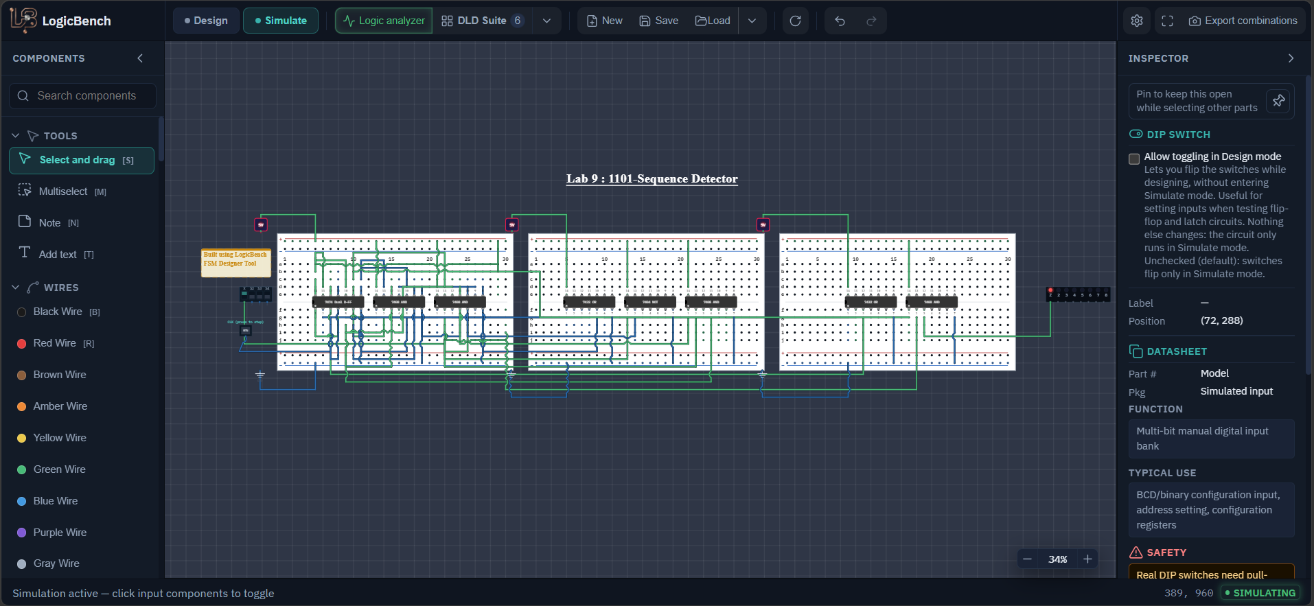
A sequence detector watches a stream of bits, one bit for every clock pulse, and raises an output when the last four bits it saw were 1, 1, 0, 1. This is the Lab 9 circuit. It is a finite state machine with four states, so it needs two flip-flops, and both come from a single 7474. The circuit was generated with the FSM Designer in the Digital Logic Suite, but it is much easier to debug if you know where every gate came from, so this page goes through the whole derivation: states, state table, flip-flop equations, wiring, and a test with real bit streams.
- CHIPS
- 7474, 4 × 7408, 2 × 7432, 7404
- GATES AND FLIP-FLOPS
- 15 gates, 2 flip-flops
- INPUTS
- Switch X and a clock button
- OUTPUT
- 1 LED (Z)
Components needed for the 1101 sequence detector
- One 7474 (dual D flip-flop), four 7408 (quad AND), two 7432 (quad OR) and one 7404 (hex inverter)
- A DIP switch with one switch in use, renamed X (the data input)
- A Push Button, which is the clock (I labelled it 'CLK (press to step)')
- A Light Bar with one LED in use, named Z
- Regulated +5V Power and Ground (GND) parts for each of the three breadboards
Open the circuit
Open the exact detector from the lab. Switch to Simulate, set X, then press the Push Button once for every bit. The LED named Z shows the detection.
1101 sequence detector state diagram
Each edge is labelled X / Z: the input bit and the output while that bit is applied. The green edge is the detection. In S3 a 1 completes 1101, and the machine goes to S1 and not S0, so overlapping patterns are still found.
Block diagram of the Mealy machine
The two flip-flops hold the state. The next-state logic looks at the present state and X and sets the D inputs. Because the output logic also looks at X directly, this is a Mealy machine.
7474 D flip-flop pin diagram
Two flip-flops in one chip. The pins with a bar over the name are active low. Notice that on the second flip-flop Q is pin 9 and Q' is pin 8, the other way round from the first one.
Timing diagram for the stream 1101101
The clock rises at the end of every bit. The state changes on that rising edge. Z is high only in the second half of the bit where the machine is in S3 and X is 1, just before the clock edge, which is why it has to be read before the button is pressed.
How to build the 1101 sequence detector step by step
Decide what each state remembers
The machine only has to remember how much of 1101 it has seen so far. S0 means nothing useful yet. S1 means the last bit was a 1 (we have '1'). S2 means the last two bits were 11. S3 means the last three bits were 110. Four states need two flip-flops, and I use the encoding S0 = 00, S1 = 01, S2 = 10, S3 = 11, written as Q1Q2.
Fill in the state table
For each state and each value of X, ask what the longest useful ending of the bits is. The finished table is below. The interesting rows are these: in S2 a 1 keeps you in S2, because '111' still ends in 11. In S3 a 1 completes 1101, so the output Z is 1, and the next state is S1, because that last 1 can start a new 1101. In S3 a 0 gives '1100', which has no useful ending, so you go back to S0. This 'last bit can start the next pattern' rule is what makes the detector overlapping.
Write the flip-flop equations
For a D flip-flop the input D is just the next value of the state bit. Read the next-state columns of the table. Q1 becomes 1 in three cases: from S1 with X=1, and from S2 with X=0 or X=1, so D1 = Q1'Q2X + Q1Q2'. Q2 becomes 1 from S0 with X=1, from S2 with X=0, and from S3 with X=1, so D2 = Q1'Q2'X + Q1Q2'X' + Q1Q2X. The output is 1 only in S3 with X=1, so Z = Q1Q2X.
Wire the 7474 first
Connect pin 14 to +5 V and pin 7 to ground. The clear and preset pins are active low, so connect pins 1, 4, 10 and 13 to +5 V to keep them inactive. Connect the Push Button to both clock pins, 3 and 11. The first flip-flop (Q1) uses D on pin 2, Q on pin 5 and Q' on pin 6. The second flip-flop (Q2) uses D on pin 12, Q on pin 9 and Q' on pin 8. Notice that on the second flip-flop Q is pin 9 and Q' is pin 8, the other way round from the first one. It is a very easy mistake.
Build the product terms and the OR gates
Use the gate-by-gate table below. In short: an inverter makes X'. A first group of AND gates makes the state products Q1'Q2, Q1Q2', Q1'Q2' and Q1Q2. A second group ANDs those with X or X'. The two OR chips then join the terms into D1 and D2, and the last AND gate makes Z.
Feed the bits in and press the clock
Switch to Simulate. Set X to the first bit, press the Push Button once, set X to the next bit, press again, and so on. Read Z before you press the button for each bit, and see the next section for why. After the fourth bit of 1101, Z should be on.
1101 sequence detector state table
| State | Q1Q2 | Next if X=0 | Next if X=1 | Z if X=0 | Z if X=1 |
|---|---|---|---|---|---|
| S0 (nothing yet) | 00 | S0 | S1 | 0 | 0 |
| S1 (seen 1) | 01 | S0 | S2 | 0 | 0 |
| S2 (seen 11) | 10 | S3 | S2 | 0 | 0 |
| S3 (seen 110) | 11 | S0 | S1 | 0 | 1 |
7474 and input pin connections
| Pin or signal | Connects to | Meaning |
|---|---|---|
| 7474 pins 1, 4, 10, 13 | +5 V | Clear and preset are active low, so they are held inactive |
| 7474 pin 14 and pin 7 | +5 V and ground | Power |
| Push Button | 7474 pins 3 and 11 | Clock for both flip-flops |
| 7474 pin 5 | Q1 | First flip-flop output |
| 7474 pin 6 | Q1' | First flip-flop inverted output |
| 7474 pin 9 | Q2 | Second flip-flop output |
| 7474 pin 8 | Q2' | Second flip-flop inverted output |
| X (switch) | 7404 pin 1, 7408 #2 pins 2 and 5, 7408 #3 pin 2 and 7408 #4 pin 2 | Data input, one bit per clock |
Next-state and output logic: gate-by-gate pin table
The four 7408 chips are numbered 1 to 4 and the two 7432 chips are numbered 1 and 2, the way they are laid out in my file from left to right.
| Chip | Pins | Computes | Goes to |
|---|---|---|---|
| 7404 | 1 to 2 | X' | 7408 #2 pin 10 |
| 7408 #1 | 1 and 2 to 3 | Q1'·Q2 | 7408 #2 pin 1 |
| 7408 #1 | 4 and 5 to 6 | Q1·Q2' | 7432 #1 pin 2 |
| 7408 #1 | 9 and 10 to 8 | Q1'·Q2' | 7408 #2 pin 4 |
| 7408 #1 | 12 and 13 to 11 | Q1·Q2' (same as above) | 7408 #2 pin 9 |
| 7408 #2 | 1 and 2 to 3 | Q1'·Q2·X | 7432 #1 pin 1 |
| 7408 #2 | 4 and 5 to 6 | Q1'·Q2'·X | 7432 #1 pin 4 |
| 7408 #2 | 9 and 10 to 8 | Q1·Q2'·X' | 7432 #1 pin 5 |
| 7408 #2 | 12 and 13 to 11 | Q1·Q2 | 7408 #3 pin 1 |
| 7432 #1 | 1 and 2 to 3 | D1 = Q1'Q2X + Q1Q2' | 7474 pin 2 |
| 7432 #1 | 4 and 5 to 6 | Q1'Q2'X + Q1Q2'X' | 7432 #2 pin 1 |
| 7408 #3 | 1 and 2 to 3 | Q1·Q2·X | 7432 #2 pin 2 |
| 7408 #3 | 4 and 5 to 6 | Q1·Q2 (same as above) | 7408 #4 pin 1 |
| 7432 #2 | 1 and 2 to 3 | D2 = Q1'Q2'X + Q1Q2'X' + Q1Q2X | 7474 pin 12 |
| 7408 #4 | 1 and 2 to 3 | Z = Q1·Q2·X | LED Z |
A full test: the stream 1101101
Z is read just before each clock press, with X already set to the new bit. This stream contains two overlapping copies of 1101.
| Bit # | X | State before clock | Z before clock | State after clock |
|---|---|---|---|---|
| 1 | 1 | S0 (00) | 0 | S1 (01) |
| 2 | 1 | S1 (01) | 0 | S2 (10) |
| 3 | 0 | S2 (10) | 0 | S3 (11) |
| 4 | 1 | S3 (11) | 1 | S1 (01) |
| 5 | 1 | S1 (01) | 0 | S2 (10) |
| 6 | 0 | S2 (10) | 0 | S3 (11) |
| 7 | 1 | S3 (11) | 1 | S1 (01) |
Other bit streams to try
| Stream | How many times Z goes on | At which bit |
|---|---|---|
| 1101 | 1 | 4 |
| 1101101 | 2 | 4 and 7 |
| 11101 | 1 | 5 |
| 110101 | 1 | 4 |
| 101 | 0 | none |
| 11001 | 0 | none |
How the 1101 sequence detector works
Why Z is read before the clock press
This is a Mealy machine, which means the output depends on the state and on the current input X. Z = Q1Q2X has an X in it, so Z goes high the moment you set X to 1 while the machine is in S3, before any clock edge. When you press the button the state moves on to S1 and Z drops again. If you only look at Z after pressing the button for the fourth bit, you will see nothing and think the detector is broken. A Moore machine, where the output depends only on the state, would instead show the detection one clock later, and it would need five states for this pattern. The Mealy version also means Z can flicker if X changes between clock edges, so it should only be read when the clock is about to tick.
The clock edge
The 7474 is positive-edge triggered, so the state changes when the button goes from released to pressed, and not when it is let go. Both flip-flops get the same clock signal, so the two state bits always change together. If you connect the clock to only one of the two pins, 3 or 11, one state bit will never change and the machine gets stuck.
Starting state and reset
In the simulator the flip-flops start at 00, which is S0. A real 7474 powers up in a random state, and in this circuit clear and preset are tied high, so there is no reset. You can still get to S0 on purpose: hold X at 0 and press the clock twice. From S1 and S3 a 0 goes straight to S0, and from S2 a 0 goes to S3 and then to S0, so two presses always get you there. A cleaner fix is a reset switch on the clear pins (1 and 13), which are active low.
Push buttons on real hardware
The simulated button gives one clean edge for each press. A real push button bounces, so a single press can look like several clock pulses and the machine will skip around the state table. Real circuits put a debounce circuit after the button, for example an SR latch built from two NAND gates. In LogicBench you do not need it, but it is the first thing to add when you move this circuit to a breadboard.
The designer's version has duplicate gates
The circuit uses 15 gates. If you compare the gate table with the equations you can see that three of them repeat something that already exists. Q1·Q2' is built twice (7408 #1, pins 4 and 5 and pins 12 and 13), Q1·Q2 is built twice (7408 #2 pins 12 and 13, and 7408 #3 pins 4 and 5), and Z is the same product as the last term of D2, so the Z gate repeats 7408 #3 pins 1 and 2. If each product were built once and wired to every place that uses it, the 8 AND gates that remain would fit on two 7408 chips instead of four, and the 3 OR gates would fit on one 7432 chip instead of two. The circuit file keeps the designer's version, so if you try the cleaner one, run it against the state table again.
Expected output of the 1101 sequence detector
- The stream 1111 never turns Z on, because 1111 is not 1101 and the machine never reaches S3.
- The stream 1101 turns Z on when X is set for the fourth bit, before you press the button.
- The stream 1101101 turns Z on twice, at bit 4 and at bit 7.
- The streams 101 and 11001 never turn Z on.
- After the clock press that ends a detection, the machine is in S1, not S0, because the last 1 may start a new pattern.
1101 detector not working? Common mistakes
Z never turns on
Check that the clock reaches both pin 3 and pin 11 of the 7474, and that pins 1, 4, 10 and 13 are on +5 V. A clear or preset pin that is floating or low holds a flip-flop in one state.
The first flip-flop works but the second one behaves strangely
Check Q and Q' on the second flip-flop. They are pin 9 (Q) and pin 8 (Q'). On the first flip-flop it is the other way round, pin 5 is Q and pin 6 is Q'.
Z is on, but it is off again after I press the button
That is correct for a Mealy output. Z shows the detection during the bit, and after the clock the machine has already moved to the next state.
The first stream works but the next one gives a wrong answer
The machine is still in the state the last stream left it in. Before every new test, set X to 0 and press the clock twice to bring it back to S0.
Frequently asked questions
How many flip-flops does a 1101 sequence detector need?
Two. The machine has four states (S0 to S3) and two flip-flops can store four combinations, so a single 7474, which is a dual D flip-flop, holds the whole state.
What is an overlapping sequence detector?
It keeps looking for the pattern while still using bits from the previous match. In 1101101 the last 1 of the first 1101 is also the first 1 of the second one, so an overlapping detector finds both.
What is the difference between a Mealy and a Moore 1101 detector?
In a Mealy machine the output depends on the state and the current input, so it goes high as soon as the last bit is applied. In a Moore machine the output depends only on the state, so 1101 needs a fifth state and the detection shows one clock later.
What are the D flip-flop equations of the 1101 detector?
With S0 = 00, S1 = 01, S2 = 10 and S3 = 11 (written Q1Q2): D1 = Q1'Q2X + Q1Q2', D2 = Q1'Q2'X + Q1Q2'X' + Q1Q2X, and the output is Z = Q1Q2X.
How do you reset the detector to the first state?
Hold X at 0 and give two clock pulses. From S1 and S3 a 0 goes straight to S0, and from S2 it goes to S3 and then to S0, so two pulses always get you there.
Try it yourself
Open LogicBench and follow along — the simulator is free and needs no account.
Launch the simulator