By Muhammad Ibrahim · Published October 27, 2026 · 7 min read
3-Input AND Gate and 3-Input XOR Gate Using 2-Input Gates (7408, 7404, 7486)
Lab 3 has two tasks and both use the same trick. A chip like the 7408 or the 7486 only gives you gates with two inputs, so when you need three inputs you chain two gates together. Task 1 is a 3-input AND with a green LED for output 1 and a red LED for output 0. Task 2 is a 3-input XOR. Both tasks read the same three switches, A, B and C, so you can watch them side by side.
- CHIPS
- 7408, 7404, 7486
- GATES USED
- 5 (2 AND, 1 NOT, 2 XOR)
- INPUTS
- 3 switches (A, B, C)
- OUTPUTS
- 3 LEDs (GRE, RED, XOR)
What you need
- A 7408 (quad AND), a 7404 (hex inverter) and a 7486 (quad XOR)
- A DIP switch with three switches in use, renamed A, B and C
- A Light Bar with three LEDs in use, renamed GRE, RED and XOR
- A Regulated +5V Power part and a Ground (GND) part for each breadboard
- Two half-size breadboards, one for each task, the way my file is laid out
Open the circuit
Open the exact circuit from the lab with both tasks on two breadboards. Switch to Simulate and flip A, B and C.
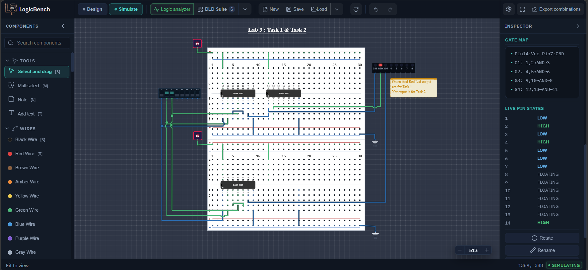
3-input AND and XOR circuit diagram
Task 1 chains two AND gates and adds an inverter for the red LED. Task 2 chains two XOR gates. Small numbers are chip pin numbers.
7486 XOR gate pin diagram
The 7486 uses the same pin pattern as the 7408 and the 7432: pins 1 and 2 into 3, 4 and 5 into 6, 9 and 10 into 8, 12 and 13 into 11.
How to build 3-input AND and XOR gates from 2-input gates
Task 1: chain two AND gates
Use the first two gates of the 7408. Connect A to pin 1 and B to pin 2, so pin 3 gives AB. Connect pin 3 to pin 5 (the first input of the second gate) and connect C to pin 4. The second gate then gives (AB)C on pin 6, which is the 3-input AND.
Task 1: add the green and red LEDs
Take pin 6 of the 7408 to the GRE LED and also to pin 1 of the 7404. The inverted signal comes out on pin 2 of the 7404, and that goes to the RED LED. Because RED is the opposite of GRE, exactly one of the two LEDs is on at any time. It behaves like a lamp that is green when all three conditions are met and red when at least one is missing.
Task 2: chain two XOR gates
Use the first two gates of the 7486. Connect A to pin 1 and B to pin 2, so pin 3 gives A⊕B. Connect pin 3 to pin 5 and connect C to pin 4. The second gate gives (A⊕B)⊕C on pin 6, and that goes to the XOR LED.
Power both breadboards
Connect pin 14 to +5 V and pin 7 to ground on the 7408, the 7404 and the 7486. In my file each breadboard has its own +5 V part and its own ground part, and the three switches are wired to both boards. If the second board seems dead, check its rails before anything else.
Switch to Simulate and run all eight combinations
Step A, B and C from 000 up to 111 and compare the three LEDs with the table below. The green LED should light only once, at 111. The XOR LED should light in four of the eight rows.
3-input AND and XOR pin connections
| Signal | Connects to | Meaning |
|---|---|---|
| A | 7408 pin 1 and 7486 pin 1 | First input of the first gate in both tasks |
| B | 7408 pin 2 and 7486 pin 2 | Second input of the first gate in both tasks |
| C | 7408 pin 4 and 7486 pin 4 | Input of the second gate in both tasks |
| 7408 pin 3 | 7408 pin 5 | AB goes into the second AND gate |
| 7408 pin 6 | GRE LED and 7404 pin 1 | ABC, the 3-input AND |
| 7404 pin 2 | RED LED | (ABC)', the inverse of the green output |
| 7486 pin 3 | 7486 pin 5 | A⊕B goes into the second XOR gate |
| 7486 pin 6 | XOR LED | A⊕B⊕C, the 3-input XOR |
3-input AND, NAND and XOR truth table
| A | B | C | GRE (ABC) | RED ((ABC)') | XOR (A⊕B⊕C) |
|---|---|---|---|---|---|
| 0 | 0 | 0 | 0 | 1 | 0 |
| 0 | 0 | 1 | 0 | 1 | 1 |
| 0 | 1 | 0 | 0 | 1 | 1 |
| 0 | 1 | 1 | 0 | 1 | 0 |
| 1 | 0 | 0 | 0 | 1 | 1 |
| 1 | 0 | 1 | 0 | 1 | 0 |
| 1 | 1 | 0 | 0 | 1 | 0 |
| 1 | 1 | 1 | 1 | 0 | 1 |
How the 3-input AND and XOR circuits work
Why chaining two gates gives a 3-input gate
AND and XOR are both associative, which means the grouping does not matter: (AB)C is the same as A(BC), and (A⊕B)⊕C is the same as A⊕(B⊕C). So you can combine any two inputs first and then bring in the third. The same idea scales to any number of inputs, you just add one more gate for each extra input. A real 7411 has three 3-input AND gates in one chip, so you could do Task 1 with a single gate if you have one.
A 3-input XOR is a parity checker
The XOR output is 1 when an odd number of inputs are 1. In the table that is 001, 010, 100 and 111, four of the eight rows. This is the basis of the parity bit. If you send the three data bits plus the XOR of those bits as a fourth bit, the total number of 1s is always even. For example 101 has XOR 0, so you send 1010, which has two 1s. And 111 has XOR 1, so you send 1111, which has four 1s. The receiver XORs all four bits and gets 0 if nothing went wrong. If one bit flips on the way, the result is 1. Two flipped bits cancel each other out and are not detected, which is the limit of a single parity bit.
Why the green LED is rare
A 3-input AND is 1 in only one of the eight rows, so the green LED is on for 1 of every 8 input combinations and the red LED covers the other 7. That is exactly why an AND is used for an 'everything is OK' lamp. One missing condition is enough to switch it off.
Gate and chip count
Task 1 uses 2 AND gates and 1 inverter, which is 2 of the 4 gates on the 7408 and 1 of the 6 on the 7404. Task 2 uses 2 of the 4 gates on the 7486. So the whole lab is five gates on three chips, and most of the gates on those chips stay unused.
Expected output of the 3-input AND and XOR circuits
- GRE is on only at A=1, B=1, C=1.
- RED is always the opposite of GRE, so one of the two is on in every row.
- XOR is on for 001, 010, 100 and 111 and off for the other four rows.
- At 011, 101 and 110 two inputs are on, so XOR is off.
3-input gate circuit not working? Common mistakes
GRE follows only two of the switches, for example A and C
The second AND gate must take the output of the first gate on pin 5, not a switch. Check that pin 3 is wired to pin 5 and that C is on pin 4.
Both LEDs are off, or GRE and RED are on together
RED comes from the inverter, so check the 7404 has power on pin 14 and pin 7 and that pin 1 of the 7404 is connected to the same signal as the GRE LED.
Task 1 works but the XOR LED is dead
The 7486 is a different chip, possibly on a different breadboard, so it needs its own power. Check pin 14 and pin 7, and check the rails of its breadboard.
The XOR LED is on for 011 or 110
That is the behaviour of an OR gate. You probably used a 7432 instead of a 7486. A real XOR is off whenever two of the three inputs are on.
Frequently asked questions
How do you make a 3-input AND gate from 2-input AND gates?
AND the first two inputs, then AND that result with the third input: (A·B)·C. Two gates from a 7408 are enough, because AND is associative, so the way you group the inputs does not change the result.
What does a 3-input XOR gate output?
It outputs 1 when an odd number of its inputs are 1, which is the rows 001, 010, 100 and 111. This is the odd-parity function, and it is 0 for 000, 011, 101 and 110.
How do you use XOR gates to make a parity bit?
XOR all the data bits together and send the result as an extra bit. The total number of 1s is then always even (even parity). The receiver XORs all the bits again and gets 0 if no single bit changed. Two flipped bits cancel out and are not detected.
How do you get a 3-input NAND gate from the same circuit?
Put an inverter after the 3-input AND. That is the red LED in this circuit: it is the opposite of the green output, so it is the 3-input NAND of A, B and C.
Try it yourself
Open LogicBench and follow along — the simulator is free and needs no account.
Launch the simulator