By Muhammad Ibrahim · Published October 27, 2026 · 10 min read
2-Bit Magnitude Comparator: Truth Table, Equations and Logic Circuit
A magnitude comparator takes two numbers and tells you which one is bigger. This circuit compares A = A1A0 with B = B1B0, two bits each, so the numbers go from 0 to 3. It has three LEDs: = when the numbers are equal, L when A is less than B, and G when A is greater than B. It is the biggest combinational circuit in my lab list, 17 gates on seven chips spread over three breadboards. It looks like a lot of wires, but if you build it in the order below it is just four small pieces.
- CHIPS
- 2 × 7404, 7486, 2 × 7408, 2 × 7432
- GATES USED
- 17
- INPUTS
- 4 switches (A1, A0, B1, B0)
- OUTPUTS
- 3 LEDs (=, L, G)
Components needed for the 2-bit comparator
- Two 7404 (hex inverter), one 7486 (quad XOR), two 7408 (quad AND) and two 7432 (quad OR)
- A DIP switch with four switches in use, named A1, A0, B1 and B0
- A Light Bar with three LEDs in use, named =, L and G
- Regulated +5V Power and Ground (GND) parts, and three half-size breadboards
Open the circuit
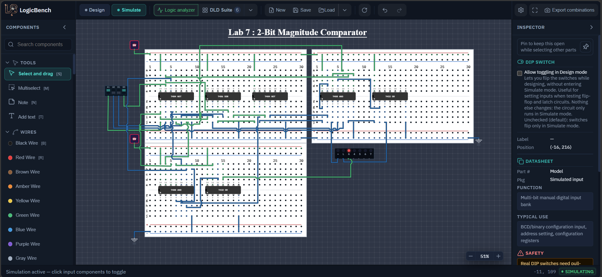
Open the exact comparator from the lab. Switch to Simulate and set A1, A0, B1 and B0. Exactly one of the three LEDs should be on.
2-bit magnitude comparator circuit diagram
The top block makes the equality signals X1 and X0 and the = output. The middle block makes L (A < B) and the bottom block makes G (A > B). X1 is used in all three. Small numbers are chip pin numbers.
How to build a 2-bit magnitude comparator from logic gates
Work out the logic the way you compare numbers by hand
To compare 2 and 3 in binary, 10 and 11, you look at the top bit first. If the top bits are different, the number with the 1 is bigger and you are done. If they are the same, you look at the bottom bit. That is the whole circuit. Call the 'top bits are equal' signal X1 and the 'bottom bits are equal' signal X0.
Make the equality signals X1 and X0
Two bits are equal when their XOR is 0, so X is an XOR followed by an inverter (an XNOR). On the 7486 connect A1 to pin 1 and B1 to pin 2, and A0 to pin 4 and B0 to pin 5. The outputs on pin 3 and pin 6 are A1⊕B1 and A0⊕B0. Send them to the first two inverters of a second 7404 (pin 1 to pin 2 and pin 3 to pin 4). The outputs of that 7404 are X1 and X0.
Make the four inverted inputs
On the first 7404 invert the inputs that the A<B and A>B terms need: A1 on pin 1 gives A1' on pin 2, A0 on pin 3 gives A0' on pin 4, B1 on pin 5 gives B1' on pin 6, and B0 on pin 13 gives B0' on pin 12. The uninverted A1, A0, B1 and B0 are taken straight from the switches.
Build the = output
The numbers are equal when both bit pairs are equal, so = is X1·X0. On the first 7408 connect X1 to pin 1 and X0 to pin 2. Pin 3 goes to the LED named =.
Build the L output (A is less than B)
A is less than B in two cases. Either the top bits decide it, A1=0 and B1=1, which is A1'·B1, or the top bits are equal and the bottom bits decide it, which is X1·A0'·B0. On the first 7408: pins 4 and 5 get A1' and B1 and give A1'B1 on pin 6. Pins 9 and 10 get B0 and A0' and give A0'B0 on pin 8. Connect pin 8 to pin 12, connect X1 to pin 13, and pin 11 gives X1·A0'·B0. Then on the first 7432 connect pin 6 of the 7408 to pin 1 and pin 11 of the 7408 to pin 2. Pin 3 of the 7432 goes to the LED named L.
Build the G output (A is greater than B)
This is the mirror image: A1·B1' or X1·A0·B0'. On the second 7408: pins 12 and 13 get A1 and B1' and give A1B1' on pin 11. Pins 9 and 10 get B0' and A0 and give A0B0' on pin 8. Connect pin 8 to pin 4, connect X1 to pin 5, and pin 6 gives X1·A0·B0'. On the second 7432 connect pin 6 of the 7408 to pin 12 and pin 11 of the 7408 to pin 13. The output is pin 11 of the 7432 and goes to the LED named G.
Power every breadboard and test all 16 rows
Every chip needs pin 14 on +5 V and pin 7 on ground. In my file two +5 V parts and two ground parts feed the three breadboards, so make sure every board has power on its rails. Then switch to Simulate and run all 16 combinations of A1, A0, B1 and B0 against the truth table.
Comparator input connections
| Switch | Connects to |
|---|---|
| A1 | First 7404 pin 1, 7486 pin 1, second 7408 pin 12 |
| A0 | First 7404 pin 3, 7486 pin 4, second 7408 pin 10 |
| B1 | First 7404 pin 5, 7486 pin 2, first 7408 pin 5 |
| B0 | First 7404 pin 13, 7486 pin 5, first 7408 pin 9 |
Comparator gate-by-gate pin connections
I call the 7404 that inverts the switches 'first 7404' and the one that inverts the XOR outputs 'second 7404'. The first 7408 and first 7432 make L and =, the second 7408 and second 7432 make G.
| Chip | Pins | Computes | Goes to |
|---|---|---|---|
| First 7404 | 1 to 2 | A1' | First 7408 pin 4 |
| First 7404 | 3 to 4 | A0' | First 7408 pin 10 |
| First 7404 | 5 to 6 | B1' | Second 7408 pin 13 |
| First 7404 | 13 to 12 | B0' | Second 7408 pin 9 |
| 7486 | 1 and 2 to 3 | A1 ⊕ B1 | Second 7404 pin 1 |
| 7486 | 4 and 5 to 6 | A0 ⊕ B0 | Second 7404 pin 3 |
| Second 7404 | 1 to 2 | X1 = (A1 ⊕ B1)' | First 7408 pins 1 and 13, second 7408 pin 5 |
| Second 7404 | 3 to 4 | X0 = (A0 ⊕ B0)' | First 7408 pin 2 |
| First 7408 | 1 and 2 to 3 | X1 · X0 | LED = |
| First 7408 | 4 and 5 to 6 | A1' · B1 | First 7432 pin 1 |
| First 7408 | 9 and 10 to 8 | B0 · A0' | First 7408 pin 12 |
| First 7408 | 12 and 13 to 11 | X1 · A0' · B0 | First 7432 pin 2 |
| First 7432 | 1 and 2 to 3 | L | LED L |
| Second 7408 | 12 and 13 to 11 | A1 · B1' | Second 7432 pin 13 |
| Second 7408 | 9 and 10 to 8 | B0' · A0 | Second 7408 pin 4 |
| Second 7408 | 4 and 5 to 6 | X1 · A0 · B0' | Second 7432 pin 12 |
| Second 7432 | 12 and 13 to 11 | G | LED G |
2-bit magnitude comparator truth table (16 rows)
A and B are the decimal values of the two 2-bit numbers.
| A1 | A0 | B1 | B0 | A | B | = | L (A<B) | G (A>B) |
|---|---|---|---|---|---|---|---|---|
| 0 | 0 | 0 | 0 | 0 | 0 | 1 | 0 | 0 |
| 0 | 0 | 0 | 1 | 0 | 1 | 0 | 1 | 0 |
| 0 | 0 | 1 | 0 | 0 | 2 | 0 | 1 | 0 |
| 0 | 0 | 1 | 1 | 0 | 3 | 0 | 1 | 0 |
| 0 | 1 | 0 | 0 | 1 | 0 | 0 | 0 | 1 |
| 0 | 1 | 0 | 1 | 1 | 1 | 1 | 0 | 0 |
| 0 | 1 | 1 | 0 | 1 | 2 | 0 | 1 | 0 |
| 0 | 1 | 1 | 1 | 1 | 3 | 0 | 1 | 0 |
| 1 | 0 | 0 | 0 | 2 | 0 | 0 | 0 | 1 |
| 1 | 0 | 0 | 1 | 2 | 1 | 0 | 0 | 1 |
| 1 | 0 | 1 | 0 | 2 | 2 | 1 | 0 | 0 |
| 1 | 0 | 1 | 1 | 2 | 3 | 0 | 1 | 0 |
| 1 | 1 | 0 | 0 | 3 | 0 | 0 | 0 | 1 |
| 1 | 1 | 0 | 1 | 3 | 1 | 0 | 0 | 1 |
| 1 | 1 | 1 | 0 | 3 | 2 | 0 | 0 | 1 |
| 1 | 1 | 1 | 1 | 3 | 3 | 1 | 0 | 0 |
How the 2-bit magnitude comparator works
Why equal means two XNORs and an AND
Two numbers are equal only if every pair of bits is equal. An XOR is 1 when its inputs differ, so an XNOR (an XOR with an inverter) is 1 when they match. Taking the XNOR of each bit pair and ANDing the results gives 1 only when all bits match. For longer numbers you simply add one XNOR for each extra bit and a wider AND.
Why the L and G terms have two parts
A < B can happen in two separate ways, so the equation has two terms joined by OR. The first term, A1'B1, is the case where the most significant bit already decides it. The second term, X1·A0'·B0, only counts when the top bits are equal, which is why X1 is in it. The G output has the same shape with A and B swapped. Notice that the equality signal X1 is used three times, in =, in L and in G, so it is built once and wired to three places.
The equations as textbooks print them
Many books expand X1 = A1B1 + A1'B1' and print the outputs without it: A > B = A1B1' + A0B1'B0' + A1A0B0' and A < B = A1'B1 + A1'A0'B0 + A0'B1B0. They give exactly the same truth table. This circuit keeps X1 and X0 as separate signals because it can reuse them in the = output and in both of the other outputs, instead of building those products again.
Exactly one LED is on
For any pair of numbers one of three things is true: A equals B, A is less than B, or A is greater than B, and only one can be true. Out of the 16 rows of the table, 4 are equal (the diagonal where A and B match), 6 are L and 6 are G. If you ever see two LEDs on, or none, something is miswired. This makes the circuit easy to debug, because the wrong row tells you which term is broken.
What the real chip does
The 7485 is a 4-bit magnitude comparator in a single package, with cascade inputs so that several can be chained for longer words. It needs the same idea as this circuit, compare from the top bit down, but the equations get longer with each bit, since every lower bit adds a term that needs all the higher bits to be equal. Building a 4-bit comparator from basic gates the way this lab does would take many more gates than the 2-bit version, because those longer terms have to be built for every bit.
Expected output of the 2-bit comparator
- Exactly one of the three LEDs is on for every one of the 16 input combinations.
- The = LED is on for 0000, 0101, 1010 and 1111, where A1A0 equals B1B0.
- A = 2 (10) and B = 3 (11) turns on L. A = 3 (11) and B = 0 (00) turns on G.
- Switching A and B around swaps L and G and leaves = unchanged.
2-bit comparator not working? Common mistakes
Two LEDs are on at the same time
One of the inverted inputs is on the wrong pin. Use the gate-by-gate table and check that A1', A0', B1' and B0' reach the pins listed for them.
= works, and L and G are right unless the top bits are equal
X1 is not reaching the lower-bit AND gates. It has to go to pin 13 of the first 7408 and to pin 5 of the second 7408, as well as to the = gate.
L and G are swapped
You have swapped A and B somewhere, or named the switches the other way round. The switch order in my file is A1, A0, B1, B0.
Part of the circuit does nothing
There are three breadboards, and each one needs +5 V and ground on its own rails. Check the rails of the board that has the dead output.
Frequently asked questions
What are the Boolean equations of a 2-bit magnitude comparator?
With X1 = (A1⊕B1)' and X0 = (A0⊕B0)': A = B is X1·X0, A > B is A1B1' + X1·A0B0' and A < B is A1'B1 + X1·A0'B0. Expanded, the usual textbook form is A > B = A1B1' + A0B1'B0' + A1A0B0' and A < B = A1'B1 + A1'A0'B0 + A0'B1B0.
How many rows does the truth table of a 2-bit comparator have?
Sixteen, because there are four inputs (A1, A0, B1, B0). Four of the rows have A = B, six have A < B and six have A > B.
How many gates does a 2-bit comparator need?
This version uses 17 gates: 6 inverters, 2 XOR gates, 7 AND gates and 2 OR gates, on seven ICs. Reusing the equality signals X1 and X0 keeps the count down.
Which IC compares binary numbers in a single chip?
The 7485 is a 4-bit magnitude comparator with cascade inputs, so several can be chained to compare longer words.
Can more than one output of a comparator be high?
No. For any pair of numbers exactly one of A = B, A < B and A > B is true, so exactly one LED is on. If two LEDs are on, or none, a wire is in the wrong place.
Try it yourself
Open LogicBench and follow along — the simulator is free and needs no account.
Launch the simulator