FSM designer — draw it or table it, either way you get a real circuit.
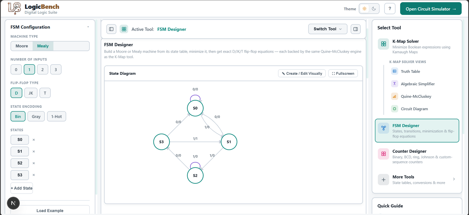
Draw states and transitions on a visual state diagram editor, or fill in the transition table directly — LogicBench keeps both in sync and derives the excitation table and exact D, JK, or T flip-flop equations either way, for Mealy or Moore machines.
This is genuinely two-way, not a diagram tool with a table bolted on: build the state diagram and the transition table, excitation table, and flip-flop equations update automatically; start from the transition table instead and the state diagram redraws itself to match. That's the part of sequential design that's hardest to keep consistent by hand as you iterate. Choose binary, Gray, or one-hot state encoding and every downstream table re-derives against it, and each flip-flop's excitation equation gets its own K-map — don't-care cells included for unused state codes — with its own Build Circuit button, not one combined black-box output. And the design doesn't stop at equations — the derived flip-flops build directly as real ICs in LogicBench's simulator, wired exactly as the excitation equations specify, so you can clock the machine through its states on an actual breadboard circuit, read it back on a synced waveform, and reuse it as a sub-circuit in a larger design.
4 steps, no signup.
Draw the state diagram or fill the table
Add states and transitions visually, or start directly from a transition table — either way works.
Pick state encoding
Binary, Gray, or one-hot — every table and equation re-derives against the encoding you choose.
Minimize and get per-flip-flop K-map equations
Equivalent states are merged, and each D, JK, or T flip-flop gets its own excitation K-map, don't-cares included.
Build the real machine
Each flip-flop equation has its own Build Circuit button, wiring real ICs you can clock through on a synced waveform.
State diagram to transition table conversion, done both ways
Converting a state diagram to a transition table — or a transition table back to a state diagram — is normally done by hand, or with a generic UML/state-machine diagramming tool that draws the shape but stops there. LogicBench's FSM designer keeps both views live: change the diagram and the transition table updates; change the table and the diagram redraws. Pick binary, Gray, or one-hot state encoding and every downstream table re-derives against it. From there it derives the excitation table and gives each D, JK, or T flip-flop its own K-map equation — don't-cares included for unused codes — and its own Build Circuit button, so you build the real sequential circuit one flip-flop at a time or all at once.
Solve it here, then wire it for real.
Every result in the Digital Logic Suite can be built directly in LogicBench’s simulator with real 74-series ICs — no retyping equations, no redrawing circuits by hand.
FAQ
What's the difference between a Mealy and a Moore state machine?
In a Moore machine, outputs depend only on the current state. In a Mealy machine, outputs depend on both the current state and the current inputs — which usually means a Mealy design needs fewer states for the same behavior, but reacts faster to input changes.
Can I design an FSM by drawing the state diagram instead of filling in a table?
Yes — the visual state diagram editor and the transition table are two views of the same design and stay in sync in both directions. Draw states and transitions, or edit the table directly, and the other view updates to match.
Does this FSM designer minimize states automatically?
Yes — it identifies equivalent states in your design and merges them, giving you the minimum-state version of your state machine alongside the original.
Which flip-flop types are supported for the excitation equations?
D, JK, and T flip-flops are all supported — choose one and the tool derives the correct excitation equations for that flip-flop type specifically, each with its own K-map showing don't-care cells for any unused state codes.
Which state encodings does the FSM designer support?
Binary, Gray, and one-hot. Switching encodings re-derives the state assignment table, the excitation table, and every flip-flop equation against the new codes, so you can compare how encoding choice changes the resulting logic.
Can I build the resulting FSM as a real, working circuit?
Yes — each flip-flop's excitation equation has its own Build Circuit button, wiring real flip-flop and gate ICs on a breadboard in LogicBench's simulator, not just a diagram. Clock the built machine through its states and read the result on a synced waveform; it can be extended or reused as a sub-circuit in a larger design.
How do I convert a state diagram to a transition table?
Draw the states and transitions on LogicBench's state diagram editor and the transition table generates automatically — every current-state/input pair mapped to its next state and output. The reverse works too: fill in the transition table directly and the state diagram redraws itself to match, so you can start from whichever form your assignment gives you.
The rest of the Digital Logic Suite.
K-Map Solver
Click cells or type an expression — get the minimized SOP, the algebraic proof, Quine-McCluskey steps, a truth table, a waveform, and a real gate-level circuit you can build with one click.
Circuit Diagram
The unsimplified and minimized gate-level schematics side by side, with exact term and gate counts — and a Build button that wires either one from real ICs in the simulator.
Truth Table Generator
The full truth table and a synced timing waveform, generated from the same expression as your K-Map, circuit, and Quine-McCluskey steps — no retyping between tools.