Counter designer — 7 counter types, lockout-checked, built as real ICs.
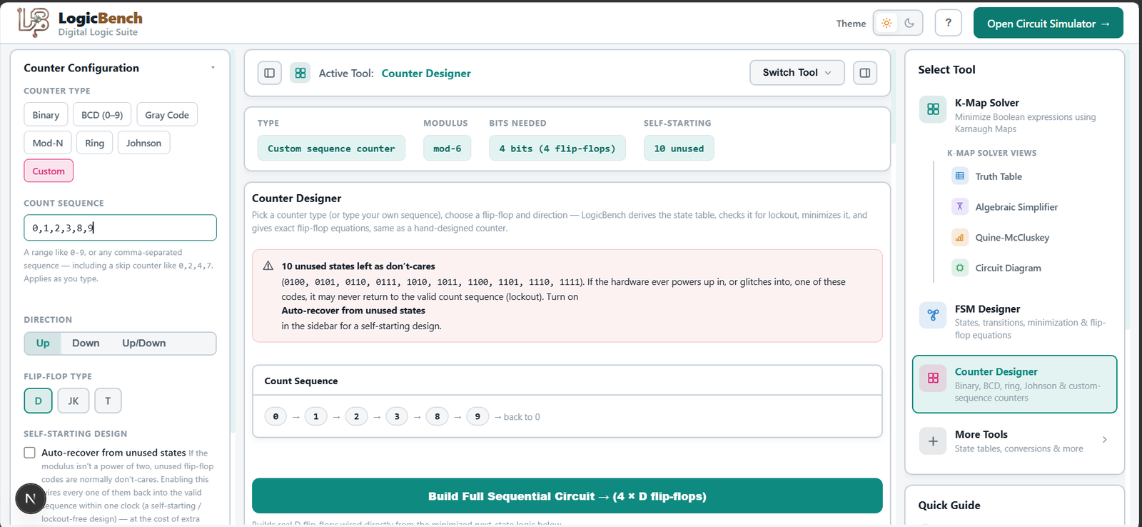
Pick a counter type — binary, BCD, Gray code, ring, Johnson, mod-N, or a fully custom sequence — choose your flip-flop and count direction, and LogicBench derives the complete design.
The parts that are easy to get wrong doing this by hand are handled automatically: unused states in a custom or non-power-of-two sequence are checked for lockout — states the counter could get permanently stuck in if it ever powers up wrong — with an option to auto-wire every unused state back into the valid sequence for a self-starting design. From there LogicBench derives the state table, minimizes it, and gives exact D, JK, or T flip-flop excitation equations, plus a synced waveform. For simple binary counters, it also shows the alternative asynchronous (ripple) design side by side — tying every flip-flop's toggle input high and chaining clocks — with the actual worst-case propagation delay tradeoff (n × t_pd for a ripple design vs. one t_pd for the synchronous version), so you can see the speed-for-simplicity tradeoff, not just take it on faith. Then, unlike a calculator that stops at equations, the counter builds as a real sequential circuit — actual flip-flop ICs wired exactly as derived — that clocks through its real sequence on a breadboard and can be reused as a sub-circuit in a larger design.
4 steps, no signup.
Choose a sequence
Pick binary, BCD, Gray, ring, Johnson, mod-N, or type your own custom count sequence.
Pick flip-flop & direction
Choose D, JK, or T flip-flops, and count-up, count-down, or up/down direction.
Check for lockout
Unused states are checked automatically, with an option to auto-recover every one into the valid sequence for a self-starting design.
Build the real counter
Exact flip-flop excitation equations are derived and built as real ICs, reusable as a sub-circuit.
Design a synchronous or asynchronous MOD-N counter, step by step
Most MOD-N counter design guidance online is a static write-up: work out the flip-flop count from 2ⁿ ≥ N, build the excitation table by hand, reduce it with a K-Map, draw the logic diagram. LogicBench does the same design process interactively — pick synchronous or asynchronous, choose D, JK, or T flip-flops, and it derives the state table, checks every unused state for lockout, minimizes the excitation equations, and builds the counter as real flip-flop ICs you can clock through its actual sequence.
Solve it here, then wire it for real.
Every result in the Digital Logic Suite can be built directly in LogicBench’s simulator with real 74-series ICs — no retyping equations, no redrawing circuits by hand.
FAQ
What is a synchronous counter?
A synchronous counter is a sequential circuit where all flip-flops are triggered by the same clock signal simultaneously, changing state together — as opposed to an asynchronous (ripple) counter, where each flip-flop triggers the next.
Which counter types are supported?
Binary, BCD (0–9), Gray code, ring, Johnson, mod-N, and fully custom count sequences — seven counter types in total, each with a choice of D, JK, or T flip-flops and up, down, or up/down count direction.
Can I design a counter with a custom count sequence?
Yes — enter any custom sequence and LogicBench checks it for lockout (unused states the counter could get permanently stuck in) before deriving the state table and flip-flop equations, with an option to auto-recover unused states for a self-starting design.
What does 'lockout' mean for a counter, and why does it matter?
If a counter's modulus isn't a power of two, some flip-flop state codes are never used in the normal sequence. If the hardware powers up or glitches into one of those unused states, an unchecked design can get stuck there forever — that's lockout. LogicBench flags every unused state and can auto-wire them back into the valid sequence.
Does this tool compare synchronous and asynchronous (ripple) counter designs?
Yes — for a simple binary counter, LogicBench shows the ripple alternative alongside the synchronous design: tie every flip-flop's T input high and chain clocks stage to stage. It also gives the actual worst-case propagation delay for each — one flip-flop delay for the synchronous version versus n flip-flop delays for an n-bit ripple counter — so the simplicity-for-speed tradeoff is a real number, not just a rule of thumb.
Can I build the counter as a real, working circuit?
Yes — the derived flip-flop excitation equations build directly in LogicBench's simulator as real flip-flop ICs on a breadboard, clocking through the actual designed sequence. The built counter can be extended or reused as a sub-circuit elsewhere.
Is there an interactive tool for MOD-N counter design, or only tutorials?
LogicBench's Counter Designer is an interactive MOD-N counter design tool — not a written tutorial you follow by hand. Enter your modulus and it works out the required flip-flop count, checks the resulting unused states for lockout, and derives the minimized excitation equations for you, for both synchronous and asynchronous designs.
The rest of the Digital Logic Suite.
K-Map Solver
Click cells or type an expression — get the minimized SOP, the algebraic proof, Quine-McCluskey steps, a truth table, a waveform, and a real gate-level circuit you can build with one click.
Circuit Diagram
The unsimplified and minimized gate-level schematics side by side, with exact term and gate counts — and a Build button that wires either one from real ICs in the simulator.
Truth Table Generator
The full truth table and a synced timing waveform, generated from the same expression as your K-Map, circuit, and Quine-McCluskey steps — no retyping between tools.